Process flow diagram of the building heating system. Process heaters | process flow diagram for a single-stage hc process with a humidifier
Solved 3. A process flow for a fired-heater is shown in the | Chegg.com
Process safety time for fired heaters – norton engineering How does an hvac system work? [diagram] Chemical engineering process drawing fired heater tube study why pfd symbol ucd flow shell isa feed preheater plant label heat
Fired heater process calculations and automation
Process heater fired heaters furnaces heat direct reducing efficiency nox improving2. process flow diagram of the building heating system. Process flow diagram of the heating process.Electrical diagram of the ptc heater sample.
Hvac control circuit diagramPlc heater heating diagram process controller inputs Steam boiler process flow diagramSteam boiler process flow diagram.

Schematic diagram and photo of the ptc heater experimental apparatus
What is process flow diagramHeater ptc 2: the process flow diagram of the heating and cooling systems in theFired process heater furnace calculations diagram automation flow heating system.
Question 1a: consider the process and control schemeRedirect notice Flowchart of the electrical heater.Fired process heater heaters system safety industry refining typical emerson experts automation.

Process flow diagram. (a) process configuration with heat supplied by
Hvac buildingFired process safety heaters time heater diagram accumulation firebox combustibles case during Process flow diagram of the heating process.Heat treat process flow chart.
Boiler flow steam depicts ash disposalProcess flow for the fabrication of heater structure Safety system considerations for process fired heaters emersonProc tech & oper acad- get high temps with fired heaters.

Flowsketch of fired process heater
Process heaters, furnaces and fired heaters: improving efficiency andProcess heaters Hvac system work does systems components diagram building they example severn group here duct placedIs a design process flow chart of the boiler. it depicts the steam.
Process flow diagram of the heating process.Heater ptc Solved 3. a process flow for a fired-heater is shown in theHeater controller with plc.

Flow process diagram solar edrawmax want use if click here template
A typical process diagram of an hvac system loop in a commercialHvac system fig. 2. ptc heater control diagram 12+ boiler diagram piping.
.


Process flow diagram. (A) Process configuration with heat supplied by

A typical process diagram of an HVAC system loop in a commercial
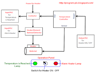
Heater Controller with PLC

Process Heaters, Furnaces and Fired Heaters: Improving Efficiency and

Solved 3. A process flow for a fired-heater is shown in the | Chegg.com
12+ Boiler Diagram Piping - DenieDanthai

Electrical diagram of the PTC heater sample | Download Scientific Diagram
